It's a fact of life that surface-mount technology is the way most things are made these days, and even at the hobbyist level it's becoming more important to be able to work with it. At Freetronics we use SMT for just about everything, and we use a variety of techniques depending on what needs to be done. The parts are so damn tiny though that it can take a lot of care to get it right.

If you have a soldering iron with an ultra-fine tip, a magnifying headset or microscope, and very steady hands, it's quite possible to solder every joint individually by hand. That's the way Marc prefers to work.
You can also do a "poor-man" version of the infra-red oven technique commonly used by professional assembly houses, resulting in very neat joints and parts that should all be correctly aligned. It's not particularly hard but you do need to follow a specific sequence, so I'll explain the steps that I (Jon) normally use when assembling SMT parts.
When I'm doing SMT assembly my work area (the kitchen table!) looks like this:

Tools Required
The five must-have items are:
Toaster oven. You shouldn't ever use it for food once you've assembled PCBs with it so you can't just borrow the one from your kitchen temporarily. I went down to my local Good Guys store and bought the cheapest one I could find, which I think was about $60. I made a round of ham+cheese toasties for the family and then got a big marker pen and wrote a warning message across the top of it.
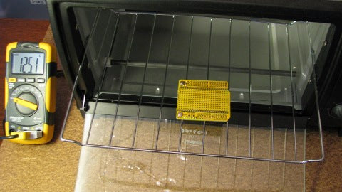
Temperature sensor. I bought a multimeter with a K-type thermocouple adaptor from Jaycar (part number QM1323, about $40), but the supplied thermocouple didn't go to particularly high temperatures and had an unprotected cable. So I also bought a 1200C thermocouple with a steel sensor tube: part number QM1282, about $15. I drilled a hole through the back of the oven and inserted the thermocouple probe through it, with the sensor area in the center of the oven just below the wire tray.

Solder paste in a syringe dispenser. This comes in either a tub or syringe, and you want the syringe. The tubs are used for loading solder-paste dispensers, but unless you're working on a production line you won't need one of those. A 30g syringe of solder paste costs about $30 from Jaycar (part number NS3038) and should last ages, since you only use a tiny amount for each joint. What you want is the stuff labeled "no clean" (or "NC") paste, which doesn't leave a corrosive residue on the board so you don't need to, well, clean it. Solder paste consists of tiny dust-sized solder balls in a liquid suspension, and needs to be kept refrigerated. It supposedly only lasts a few months after being opened but should be fine for a year or two.
Very fine non-magnetic tweezers. You'll need to place parts that are small enough to lose in the palm of your hand and if the tweezers are even slightly magnetised the parts will stick to them and you'll go slowly insane. I bought some super-fine non-magnetic tweezers from - you guessed it - Jaycar. Part number TH1754, about $5.

Magnifier. This could be a big illuminated magnifying lens on a stand, a magnifying headset, or (my favorite) a stereo zoom microscope. I got mine second-hand for about $260, and it was the best thing I've bought for a very long time. It does continuous zoom from 8x to 40x, but I find that I leave it zoomed out at 8x almost all the time. At that level I can still only see a small part of the PCB and in fact it would probably be ideal to have something that zooms from about 4x to 20x. Being stereo is important, by the way: it means you'll have depth perception while using it, which is critical when you're trying to put solder paste onto a pad about 1mm square without making a big mess. Oh yes, and you need to make sure you have lots of illumination. A high-intensity desk lamp with the head angled down directly onto the work area should do fine.

Solder Paste Placement
Take the solder paste out of the refrigerator, put your PCB under the microscope, and let's get started.
I always keep a square of paper towel next to the microscope and start by squeezing out a small amount of solder paste onto the paper to get it flowing smoothly. Make sure you keep the tip of the dispenser clean by wiping it off with the paper towel whenever it starts to get messy.
Squeeze out a little dot of solder paste onto each of the pads on the PCB. It'll feel a bit odd the first time you try it, but after a moment of practice you'll get the feel for it. I find that once the paste is flowing it will tend to keep moving slowly under gravity, so if you don't put quite enough onto a pad with a quick sqeeze you can just hold the dispenser in place for a few seconds and let the paste ooze out by itself.
Solder paste doesn't look anything like you expect: it comes out as a sort of grey goo, and it's hard to imagine it turning into a solder joint.

One interesting aspect of working with solder paste is that you don't actually need to get it cleanly onto each pad separately. When it melts it will be pulled onto each pad individually by surface tension, and as you'll see in a moment it tends to slump together into a grey mass during the "ramp" heating phase anyway. For simple 2-terminal parts such as resistors and capacitors you can just run a single bead straight along where the part will go, and it will magically separate onto the pads when the solder melts. I always put it on each pad individually anyway just because that helps me gauge how much I'm putting on.
Likewise for many surface mount ICs you can just run a bead of paste straight along each row of pins, not even bothering to try to keep each pin separate. Then just plonk the IC into place in the grey goo, and watch in amazement as it suddenly pops into the correct position and the solder around each pin splits into a separate joint when the solder paste melts.
Once you've applied solder paste to all the pads, stick the cover on the syringe and pop it back in the fridge for next time.
Parts Placement
Once the board has been all pasted up you need to place each of the parts. You shouldn't leave the board out indefinitely or the paste will dry out, and generally it's a good idea to get the board populated and into the oven within about 30 minutes of starting to place the paste.
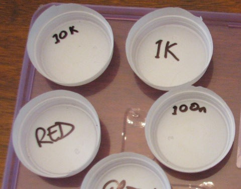
To keep all the parts handy during placement I use bottoms cut out of disposable plastic coffee cups, each one labeled with a Sharpie to show what goes in it. Then I tip the appropriate number of parts into each cup base.

My friend Bdale Garbee uses almost the same technique, but he uses a mini cupcake tray instead. A cupcake tray is more stable and less likely to be accidentally bumped over, but I find that having separate cups for each type of part is handy because I can gently flick it up in the air to turn over any parts that are upside down - a bit like flipping a pancake, but on a microscopic scale! Using a cupcake tray you need to rotate parts by picking them up once with tweezers, putting them down the correct way, and then picking them up again.
There are many techniques for parts handling and it's really just a matter of finding a method that works for you.
However you do it, pick up each part using your non-magnetic tweezers and place them into the solder paste on the PCB. Try to get each end of the part "wetted" into the paste so that it adheres to it, otherwise you may have problems with the parts "tombstoning" when the paste melts and surface tension is applied more on one end of the part than the other. Tombstoning is when a part flicks up on one end and stands upright with the other end disconnected from the board, and it's really annoying.

Notice how the parts are a bit crooked? That doesn't matter. As mentioned above, surface tension will pull everything nicely into alignment when the solder paste melts.
Baking The Board
Now for the fun bit. Turn on your temperature probe and put the PCB on the wire tray somewhere near the center of the oven. The ideal situation is to have the board heat evenly, so placing it approximately equidistant from the heating elements is a good idea. I usually do two or three boards at a time, but don't overdo it. My oven seems to get hotter on the right and center, with the left side lagging behind, so I tend to place my boards slightly to the right. How do I know that? Read on and all will be revealed.
The photo below shows a Freetronics prototyping shield in the oven ready to go, and you can see the metal probe of the high-temperature thermocouple poking in through a hole in the back of the oven.

Solder paste is not designed to be just heated up fast and immediately cooled down again. You should bake it using what is known in the trade as a "reflow oven profile", which is a temperature curve designed to minimise bad effects such as sputter. Sputter is when the solder paste heats unevenly and little pockets of flux and liquid carrier boil out of it with a "pop", splashing microscopic dots of solder around the joint.
The usual profile is called a "ramp, soak, spike" profile, and looks something like this diagram taken from the datasheet for the solder paste sold by Jaycar:

The "ramp" stage is the initial upward gradient that takes the oven quickly up to a temperature that's about 20C below the melting point of the solder paste. The "soak" stage is the flat section in the middle where the temperature is held steady for up to 2 minutes at that temperature, giving the PCB and all the parts on it a chance to stabilise at a uniform temperature just below the melting point of the solder, and letting the solder paste's liquid carrier evaporate away. The "spike" stage quickly punches the temperature up to at least 20C above the melting point of the solder, then the cooling stage brings it down quickly again to room temperature.
It may sound complicated but don't worry, it's not. Just follow these steps and everything will be fine. You may need to adjust the temperatures at which you do things depending on the performance of your oven, solder paste, and thermocouple, but this is the process that has worked well for me.
1. First I turn the oven on full, watching the temperature display until it hits 85C. I then turn the oven off, and because of thermal lag and the heat in the heating elements the temperature then continues to coast upwards. This is the "ramp" stage.
2. As soon as the temperature passes 100C I consider it to have entered the "soak" stage and start a timer (well, actually I count "one mississippi, two mississippi, three... very high tech) and count off between 90 seconds and two minutes, depending on how impatient I am. The temperature will continue to coast up during this stage, and for my oven it peaks at about 115C and sits there for a while.
3. Once the two-ish minutes has passed I turn the oven on full again, beginning the "spike" stage. This is where things get really interesting. Keep your eye on the solder paste and watch it very closely, because any moment now the magic event will happen and joints will suddenly flash from dull grey to bright silver. As soon as that happens I turn the oven off again, but once again thermal inertia will keep the temperature climbing for a while. Watch until all the joints have turned silver and the SMT parts have been pulled straight by surface tension, then give it a few more seconds to be on the safe side, then...
4. Open the oven door to begin the cooling stage. The temperature in the oven should start to fall very rapidly, but whatever you do don't touch anything (or even bump the oven) until the temperature has fallen below about 130C. The solder will still be molten, and if you bump anything you can seriously burn yourself or (worse still) knock parts out of alignment on the board.
Once the indicated temperature has fallen below 130C I use a pair of pliers to grip the wire tray and gently slide it half way out, giving air circulation a chance to cool the PCB down even more quickly.

That's it! Let it sit there for a few minutes so you don't scald yourself, then pick it up carefully and put it on some paper towel or similar to continue cooling to room temperature. Then stick it back under your microscope to inspect the joints and you should find they're all neatly soldered and your board is ready to go.

One thing to check for is that your oven's wire tray is sitting level. You'll see in the photo above that the solder blobs toward the front of the PCB are bigger than the ones toward the back. That's because the tray in my oven tilts towards the front, and so when the solder paste around each pad melts and separates onto the individual pads it will tend to flow slightly more to the front pads than the back. Most of the time it's not as obvious as this, but I happened to do a particularly poor job of applying the solder paste in this demo because I was trying to work around a camera lens that was about 15mm from the PCB and blocking my view while I was putting on the paste!
Feedback?
Got a comment or suggestion about this tutorial? Shoot us an email!


