Note: the Security Sensor Shield kit is based on the "Security / Automation Sensors" project in the book "Practical Arduino". For a detailed discussion of the operation of the circuit please see the book.
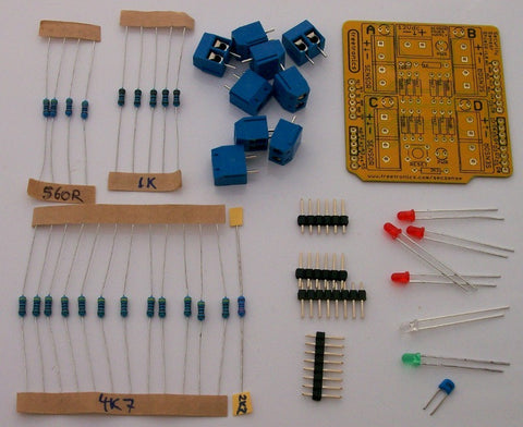
The Security Sensor Shield has been designed for easy assembly and you may find you can assemble it simply by following the overlay printed on the PCB. Even if you have no previous experience with electronics you should be able to get through it by following this guide.
Note that this guide does not attempt to teach you how to solder: if you've never soldered before, please see How To Solder.
Step 1: Check / Identify Required Parts

| Qty | Part |
| 4 | 390R resistor |
| 5 | 1K resistor |
| 1 | 2K2 resistor |
| 12 | 4K7 resistor |
| 4 | Red 3mm LED |
| 1 | Blue 3mm LED |
| 1 | Green 3mm LED |
| 1 | 100nF ceramic capacitor |
| 9 | 2-pin PCB-mount screw terminal |
| 1 | SPST PCB-mount tactile button |
| 2 | 1x6 male break-away header |
| 2 | 1x8 male break-away header |
| 1 | Security Sensor Shield PCB |
Step 2: Resistors
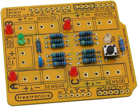
Start by fitting the lowest parts: the resistors. They all lie flat on the PCB, so it's easiest to fit these before other higher parts get in the way. Resistors aren't polarised so it doesn't matter which way around you install them, but it's customary to fit them with the colour codes all aligned in the same direction to keep everything neat and make the values easier to read.

Bend the legs of each resistor 90 degrees before inserting them into the appropriate locations on the PCB. Once each resistor has been inserted, bend the legs out at about a 45 degree angle under the PCB to hold them firmly in place before soldering them on and cutting off the excess lead length.
Note that only four of the 4K7 resistors need to be fitted to the PCB. The other eight are supplied for you to use at the sensors: each sensor needs two 4K7 resistors to implement the End-of-Line functionality. Put them aside for now and we'll get back to them when it's time to connect the sensors.
The four 560R resistors labelled on the PCB have been replaced in the kit with four 390R resistors. Those resistors limit the current supplied to the red LEDs, and we found that the available LEDs were a little bit too dim with 560R resistors. Replacing them with 390R resistors allows more current to flow through each LED and therefore makes them a bit brighter.
Step 3: LEDs, Capacitor, and Button
Next fit the button. It has four pins that are spaced so that it will only click into the PCB holes the right way, as shown in the photo. Don't bend the legs to force it to fit 90 degrees out of position or the shield won't work.


LEDs are polarised so you need to take care to fit them with the correct orientation. Each one has been marked on the PCB with a small “+” symbol to indicate the position of the positive (anode) pin, which is the longer pin. Push the LEDs down flush with the PCB, bend out their legs at an angle, solder them in place, and cut off the excess.
Step 4: Screw Terminals and Headers
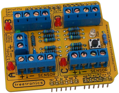
The screw terminals are supplied in 2-terminal units, and they have a tiny V-shaped ridge on one end and a matching groove on the other. Slide eight of them together into four sets, and fit / solder them to the PCB. You may find it easiest to use sticky tape or blue-tac to hold them on the PCB while you solder the pins in place.

Because the Security Sensor Shield requires connections to come in from the sides, it's not possible to use it with stacking headers to mount another shield on top. It has been supplied with regular break-away headers, and the easiest way to fit them and have them correctly aligned is to insert the headers into your Arduino and then sit the shield on top. You can then solder the top of each header to the shield PCB, and when you remove it from the Arduino they will all be neatly aligned.
Step 5: Connect Sensors
Each sensor should be connected to the shield using a 4-core security cable. One pair of the cable is used to carry 12Vdc power to the sensor, and the other pair is used to detect sensor status.
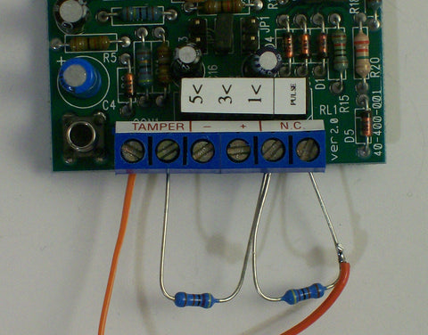
Each sensor is connected using two 4K7 resistors, with one resistor across the “normally closed” output terminals and the other between one NC terminal and one of the tamper terminals as shown in the photo.

You can either insert the resistors into the screw terminals as shown, or solder them permanently onto the back of the sensor PCB to make it easier when fitting the wires and mounting the sensor in place.
Step 6: Connect 12Vdc Power Supply
If your sensors require a power supply you can connect the output from a 12Vdc plug pack or other power supply to the “Sensor Power Supply” screw terminals on the end of the shield. Applying power to the plug pack will cause the green LED to illuminate, and sensors connected to the + and – terminals will power up.
Step 7: Load Test Sketch
The Security / Automation Sensors project in Practical Arduino includes a sketch that you can use to test the operation of the shield. It displays the current status of each sensor channel via the serial terminal, and can be downloaded from:
https://github.com/practicalarduino/SecuritySensorsSchematic
This partial schematic shows the connections to one of the four sensor channels. Each channel is simply a duplicate of this circuit.


