Many Arduino shields are shipped with headers packed loose, leaving it up to you to solder them in place. Sounds easy, right? Actually, it’s more fiddly and annoying than it sounds. Arduino headers consist of four separate headers, and if you get the pins even a little crooked on any of them it can be hard getting the shield to plug neatly into the Arduino. The first few times I soldered headers to shields it took several minutes of cursing, burned fingers, and repeatedly re-flowing the solder on the first joint to get them to sit perfectly straight before soldering the rest of the pins.
But luckily there is a way to do it quickly, easily, and with perfect results every time! This technique works in a very similar way for both regular “male” break-away headers, and also for stackable headers. When you see how easy it is you’ll wonder why you ever tried doing it any other way.
Regular Male Headers
What you’ll need:
- Your shield (derr!)
- 2 × 6-pin and 2 × 8-pin male headers
- An Arduino
- Solder and soldering iron
Sit your Arduino down flat on your workbench and insert the header pins into the headers, pushing them down flush. The picture below shows an Arduino mounted on a piece of timber using plastic spacers and screws so it’s nice and stable, but that’s overkill.

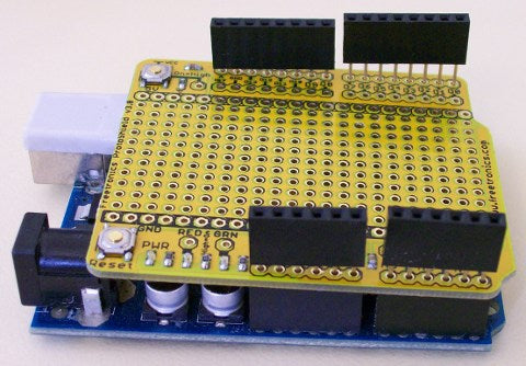
Next, put your shield PCB onto the headers so that it sits down on the Arduino in the position it would normally be when fully assembled. You can see where this is going, right?

Now just solder all the header connections on the top of the PCB to attach the headers to the shield, pull the shield off the Arduino, and you’re done!
The result should be headers that are perfectly straight and mounted flush, ready to fit into your Arduino.
Stackable Headers Using Another Shield As A Jig
Stackable headers are cool because they provide regular male pins on the bottom of the shield and female headers on top, letting you attach multiple shields to an Arduino simultaneously. Great in theory, but they can be even more of a bugger to solder than regular headers! Unlike regular headers they have a plastic body on the top of the shield, requiring you to solder them from underneath. If you’ve ever tried to do it you’ve probably felt like you needed about 5 hands to keep everything in place.
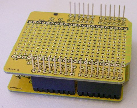
The solution is to use another shield (if you have one) as a guide. Lay a shield upside-down on your bench with its header pins sticking straight up, and then plug the stackable headers onto them.

Now turn the PCB for your new shield upside-down and slide it down onto the stackable header pins so the bottom of the PCB is exposed.
Because stackable headers usually use rectangular-section pins that are thinner than normal square pins you may find that they’re still not quite straight. There’s often enough space in the PCB holes for the header pins to move sideways, so sight along them and wiggle them a bit if necessary to get them standing up straight.

The final step is obvious: solder each pin to the bottom of the shield PCB, slide it off the shield you were using as a guide, and you’re done!
One little gotcha is not to let the solder go too far up the pin: try to keep it down near the PCB. It’ll naturally tent up a little and form a cone around the pin, but try not to smear it up the pin unnecessarily. The pin needs to slide into the header on your Arduino, and excessive solder can get in the way.
Stackable Headers Using An Arduino As A Jig
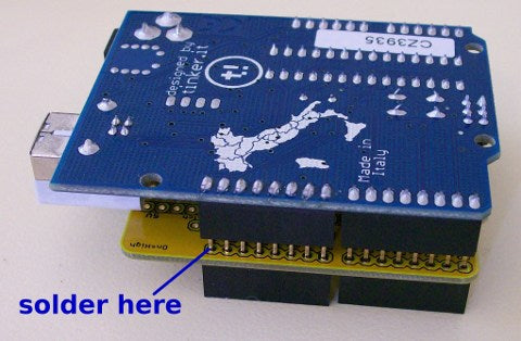
But what if you don’t have another shield lying around to use as an assembly jig? Well, you can also use your Arduino to do the same thing but it won’t be as easy. First sit your shield PCB on top of the Arduino as if you were going to mount it, but without the headers in place. Then slide the stackable headers down through the shield PCB into the Arduino so it’s “pinned” in place, but still not connected to the headers.

There will be a space between the shield PCB and the Arduino because stackable headers don’t have a plastic spacer under the board.
Now turn the whole assembly upside-down so that the Arduino is on top and everything is sitting on the stackable headers, then make any final adjustments to get the spacing correct.
Finally, solder the pins in the small gap between the Arduino header and the shield PCB as shown below.

Try not to melt the Arduino headers! It’s probably best to just solder the end pins, then remove the Arduino and solder the rest of the pins in place when you have easy access to them.
Stackable Headers Using A Clamp
Another approach is to place the stackable headers through the holes in the PCB, then place the PCB (and headers!) upside down on a flat surface such as a table. Because the top of the plastic shroud on the headers is flat they will naturally tend to sit straight, and you can use a weight on top of the shield PCB or a very gently clamp to hold everything in place. One downside of this method is that there is some lateral slop in the position of the stackable headers, so you'll need to make sure you get them aligned in the center of the PCB holes.
Feedback?
Got a comment or suggestion about this tutorial? Shoot us an email!


